


bods
Member
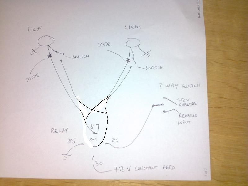
Yeah sorry, it may actually be called spdt ( single pole double throw) because it works both ways... anyway, have a look at this and tell me what you reckon
You can stick fuses wherever you like, but if the wiring is out of danger its up to you if you use them. Not much else I can say really, that's probably the way I'd do it... Just run twin core to the lights for the 2 power feeds so you can split them wherever you want to put the lights.
Sorry, should have said. 87a would be the feed for the switches at the actual lights as that will have power when the relay is "off", 87 for the in cab switch so when the relay is "on" the lights both come on
Last edited:


