Super urgent help needed - Power chip

Nissan Navara Forum

Help Support Nissan Navara Forum:

This site may earn a commission from merchant affiliate links, including eBay, Amazon, and others.

180%JOE

Member
Joined
Jun 2, 2009
Messages
241
Reaction score
0
Location
Brisbane
Hi all,
Im in urgent need of help with the installation of a diesel power module!
Can anyone post pics of the correct wires to tap into on their ecu and fuel pump?

Where ive done it seems right by the instructions but now the nav dosen't rev past 2500rpm?? I have to work tonight and need to fix this asap.

Any help appreciated!

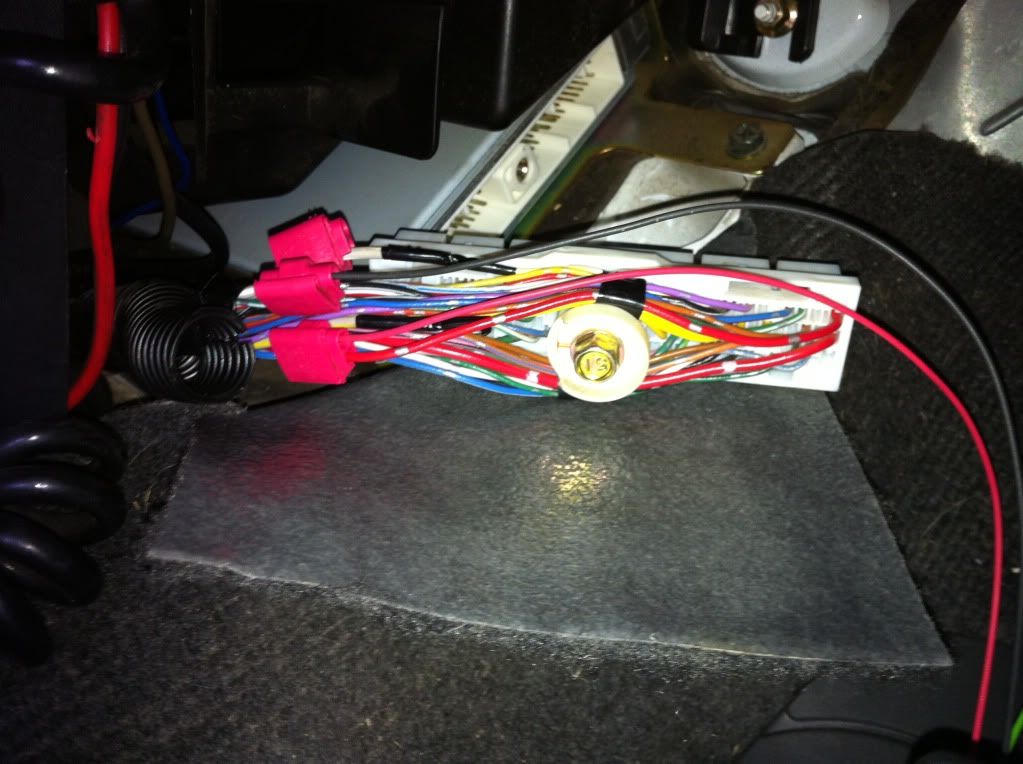
These are some pics where ive tapped into:

IMG_0224.jpg

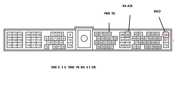
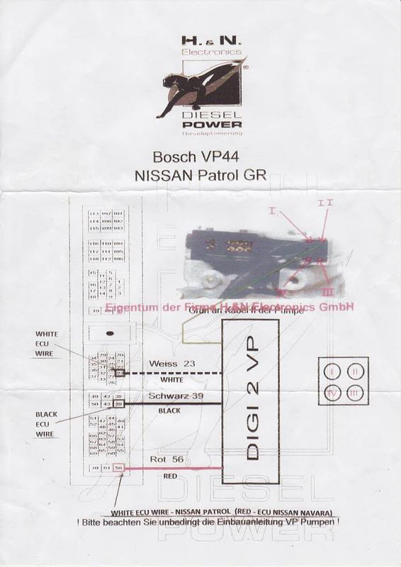
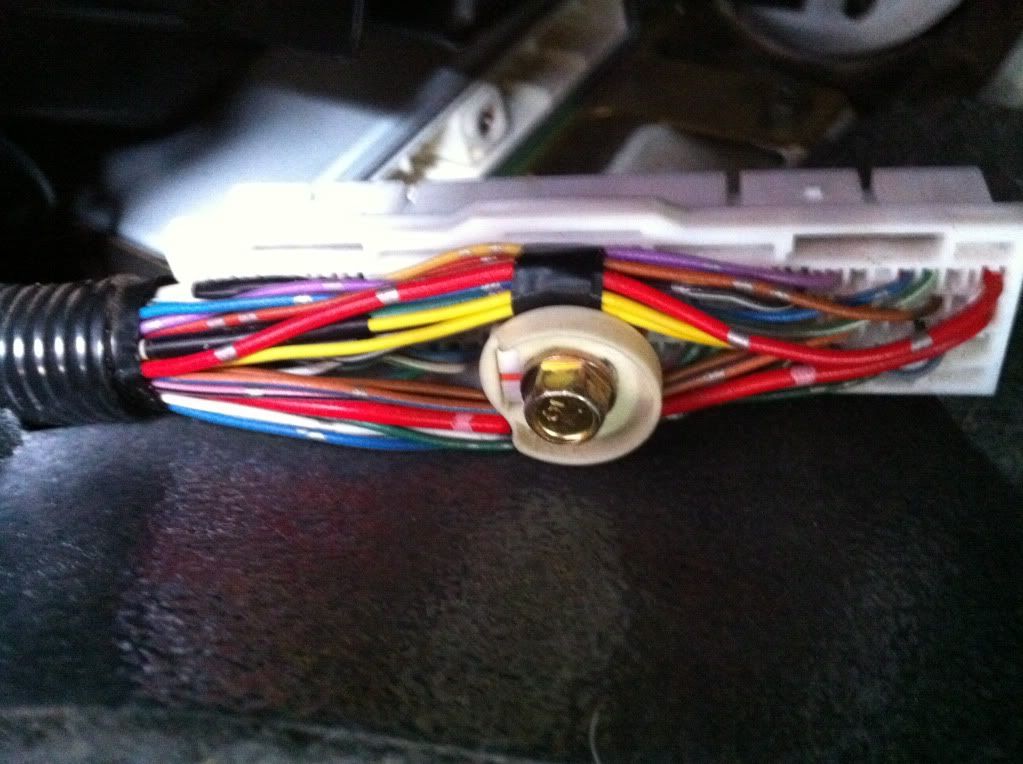
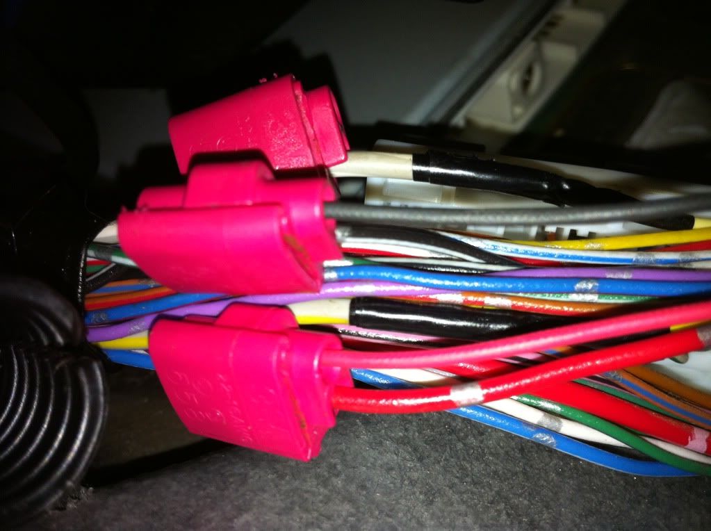
This is the three for the ecu, red, black and white

IMG_0197.jpg

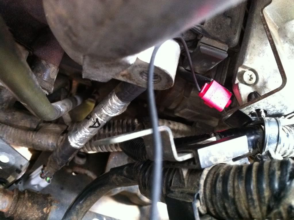
This is the one to the fuel pump is this correct? it connects to a green wire on the power chip


IMG_0221.jpg


IMG_0222.jpg
 
Also this is a diagram of the ecu harness and where the wires are meant to go, looking from the wire side.

ECMPIN.jpg


and here are the instructions i got with the chip:

instructions.jpg


instructions2.jpg
 
Last edited:
Can't help with connections apart from suggest you take the chip back out tonight.

But I would suggest you dont use scotchlocks for something so important, they won't last long til it all fks up!

Solder & double heat shrink
 
Did you try calling 0416 389 644?
Direct them to here for images and see if they can help.
 
Your engines in limp mode. I would disconnect it for tonight until you get assistance.

Try disconnecting the battery, hold foot on brake, then reconnect battery, to do a full ECM reset.
 
I haven't called the help number yet I'll do that tomorrow.
The scotch locks were the prefered option to soldering I was
Told so that it is more easily reversible. I tried without the chip plugged
To the harness and it's still in limp mode. I'll try resetting the
ECM tomorrow as well.
 
I took the nav to an auto electrician and their advice was to take it off as they were too busy to even come out and have a look at the wiring! I mean ten steps to my truck was too difficult... they told me that if i was still having trouble they could fit me in next week. Well after that I disconnected the wiring harness and the nav was back to normal. I then called the "help" number and he couldn't do anything really! I showed him the photos and His suggestion was to tell me that a few harnesses they sent out a while back were wired wrong and some of the pins may be in the wrong place. So he sent me a diagram in German! I'm pulling my hair out! for something that they claim is simple DIY and 15mins don't believe it.

There must be someone out there with a power module that could post some pics of the wiring????
 
I have a DP chip and it only has 2 wires gong to the ecu and the 1 to the fuel pump. Grey goes the pin23 and red goes to pin61. don't know if this is any help.
 
im not sure about the module that you have, but I presume it works the same as the dp chip etc (4 wires). you will probably have a +12V (in your case probably red), a gnd in your case probably black), a wire to the pump (in your case green) and a wire to the accelerator position (in your case probably white).

I would start by checking what the red and black wires are connected to. the balck should be the gnd of the system, check the continuity between the terminal you are connecting to and the body of the car somewhere. The red should have 12V on it when the car ignition switch is on.

Then I would check the terminal you are supposed to be connecting the white wire to. If it works in the same way that the other chips do, you should have a signal on this pin ranging from about 0 to 4.5 volts. Put your meter on this pin and press the accelerator down (with the ignition on, but not engine running) Do you get the 0 to 4.5V?
I have a tunit chip and from memory the diagram was not real intuitive, so I had to hunt a round a bit on the ECU loom to find this signal. When I found it, the diagram then made sense. So see if you can find the 0-4.5V signal and see if it matches up with the diagram that came with your kit.

Lastly, the green wire to your fuel pump should probably connect to the top right hand corner wire if looking at the back of the fuel pump.

Something else to try, try disconnecting one at a time the green wire and white wire. ie have the red, black and white wires connected, does the problem go away? then do the same with the green wire, this should eliminate one of these.

Does your kit come with a wiring diagram that describes the functions of the wires connected to your module, ie the red, black, green, white?

Any questions, let me know.
 
Well I made sense of the module harness diagram and the pins are in the correct places. I only have a test lamp so for now I tested the red 12volt wire and this is the correct connection. Tomorrow I will buy a multimeter and test the other wires. Thanks simonk8 at least I have a plan now.

failing this I will re-connect the harness how I had it originally and start with the module at it's lowest setting? my theory is that the setting they recommend may be putting the nav into limp mode with my other mods ie. exhaust and filter. Then if it works i will adjust the power mode up one at a time.
 
I still cant get it working :( but I did get a call the other day from a guy from turbo australia to help me with fitting the chip. It was too hard to explain what I had done so ive got to take it to them at darra to see if they can help me..... This is turning into a huge mission for a simple "diy" job.
 

Latest posts

Back
Top