Turbo Conversion

Nissan Navara Forum

Help Support Nissan Navara Forum:

This site may earn a commission from merchant affiliate links, including eBay, Amazon, and others.
Alright time for an update!

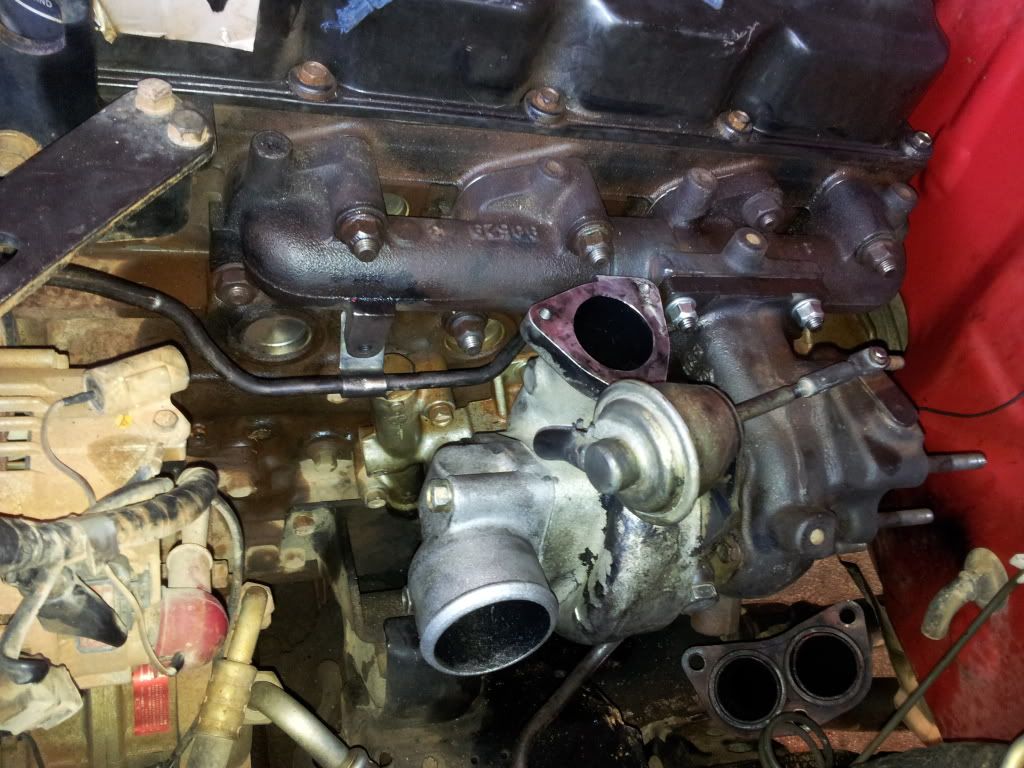
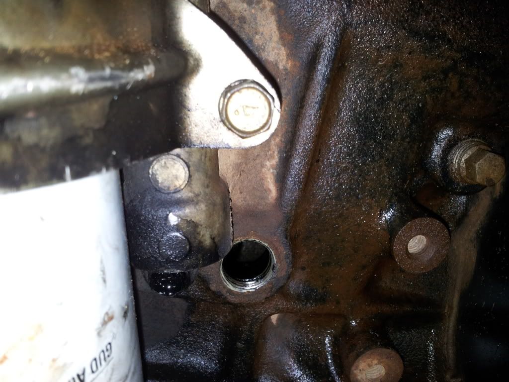
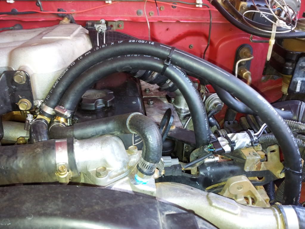
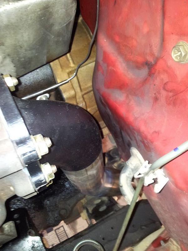
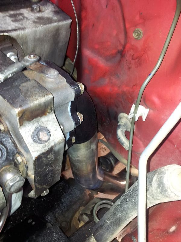
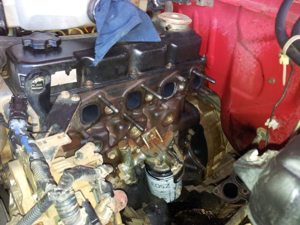
Got cracking and pulled off the exhaust manifold, applied ample amounts of WD 40 and it came off reasonably easy.
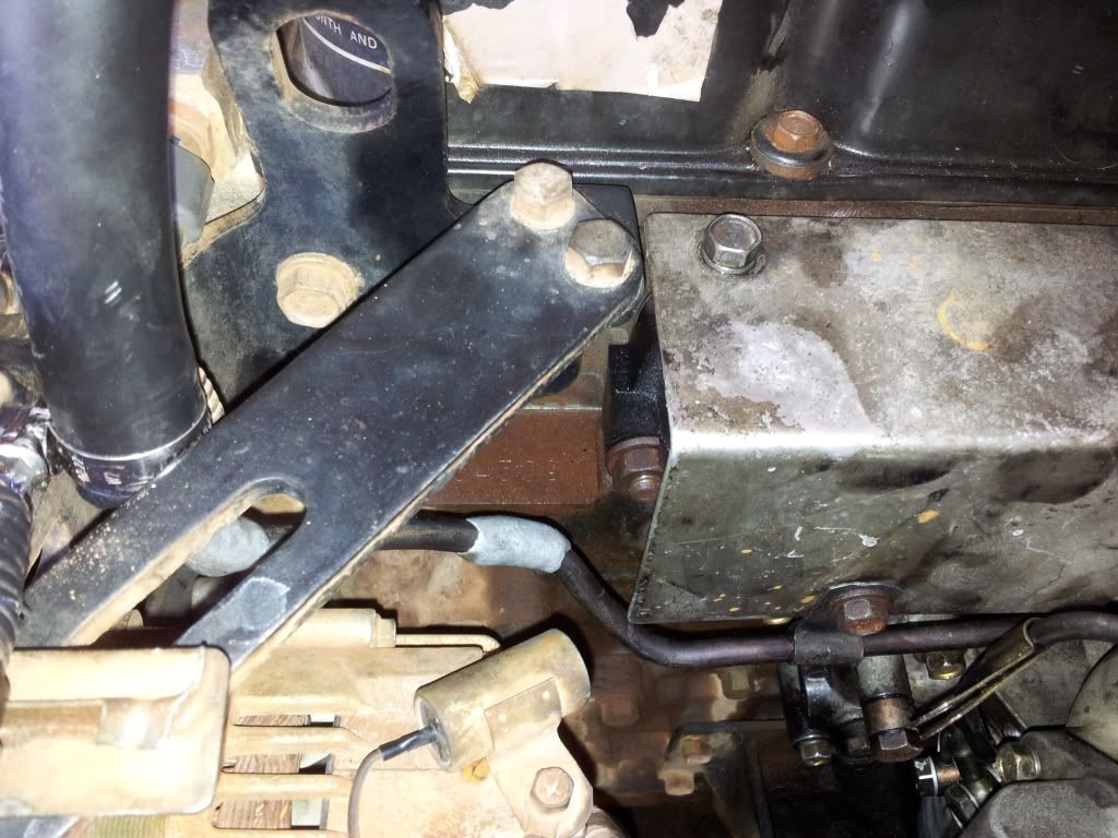
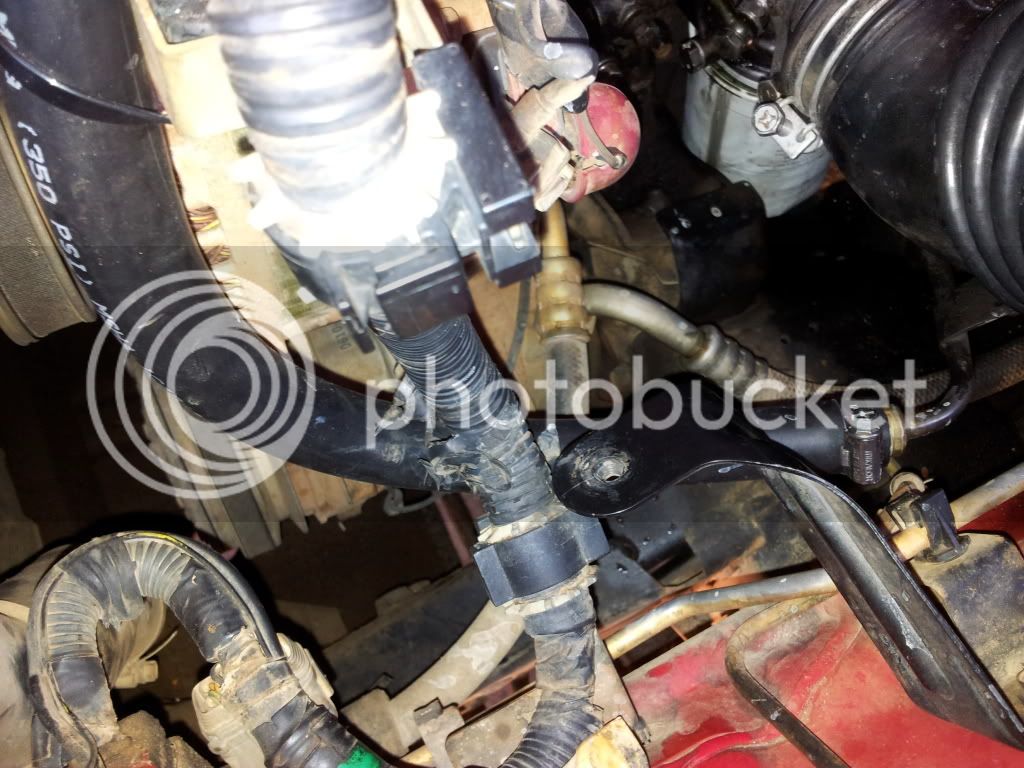
Had a tonne of difficulty getting the manifold to disconnect from the exhaust but eventually solved that by disconnecting the length of exhaust behind the flexible coupling which allowed me to pull it up high enough to get some leverage on those bolts which were tightened up good and proper.

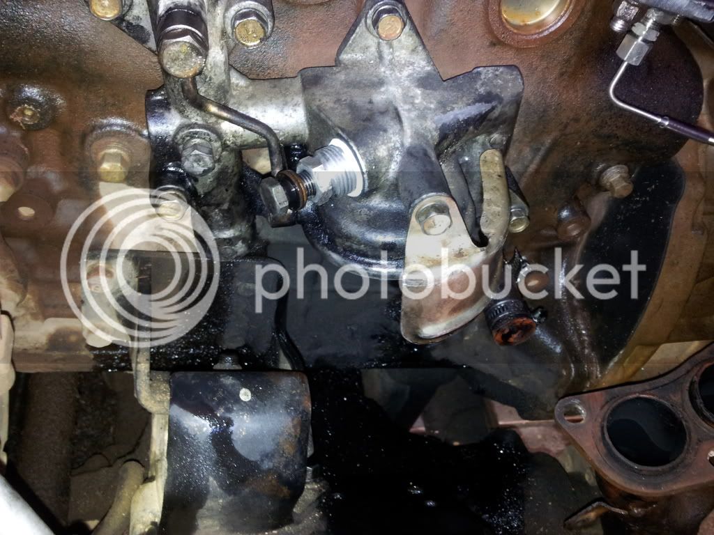
I had to replace 4 of the studs as they were too short to be used on the TD27T exhaust manifold. These can be gotten from Nissan however I think they are pricey, if you are pulling the turbo and manifold from a wrecked car make sure you grab the long studs too!

I had to replace a couple of the studs from turbo to the exhaust manifold which had sheared off, these took a bit of work with an oxy torch but evenetually came off, Nissan sold them to me for 12 bucks a pop so avoid this if you can.

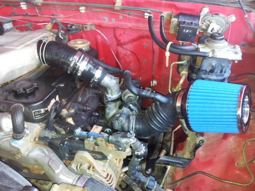
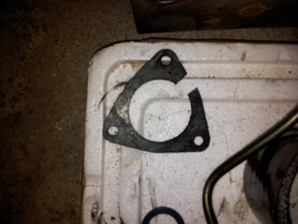
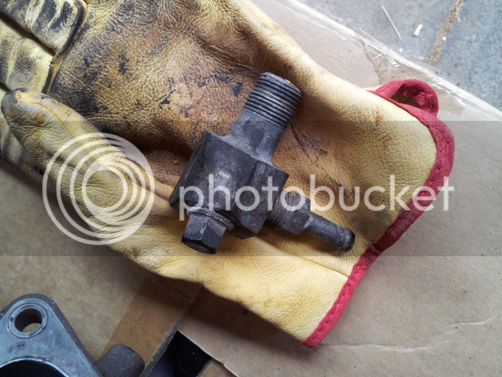
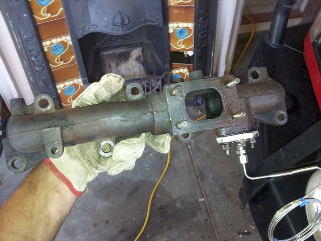
Ive then fashioned a very amateur blanking plate to cover up the EGR port which I have no need for and welded on a BSP fitting to take a EGT sensor, you will have to forgive my shoddy welding hehe. Im using a racetech gauge that I ordered here.
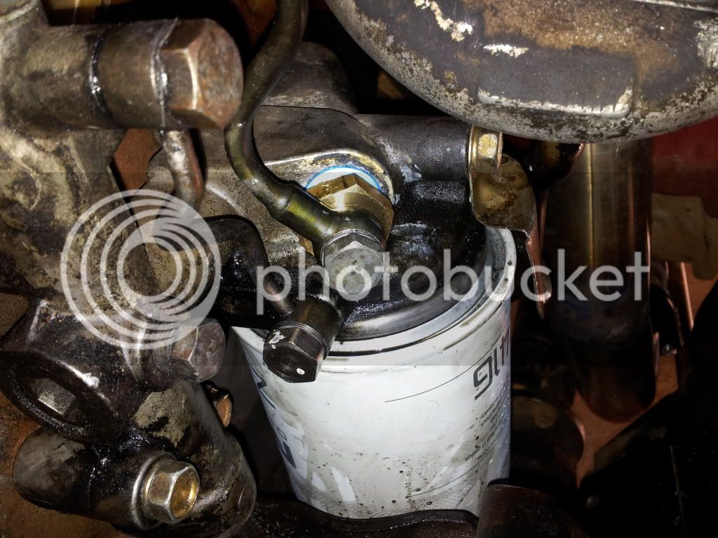
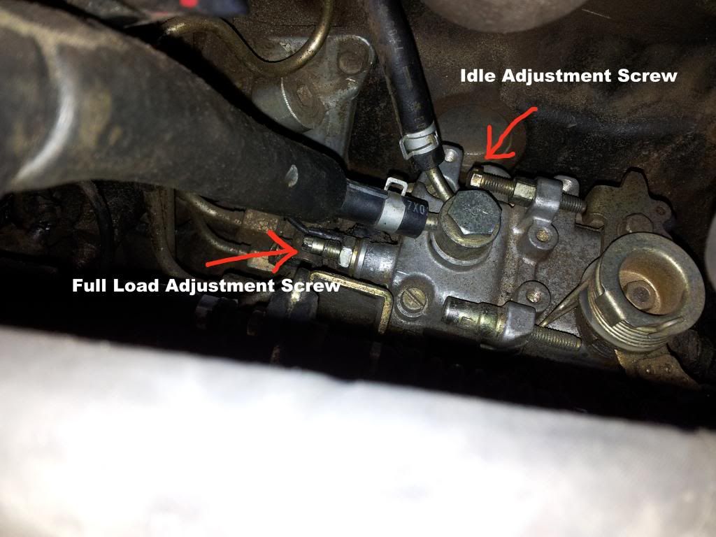
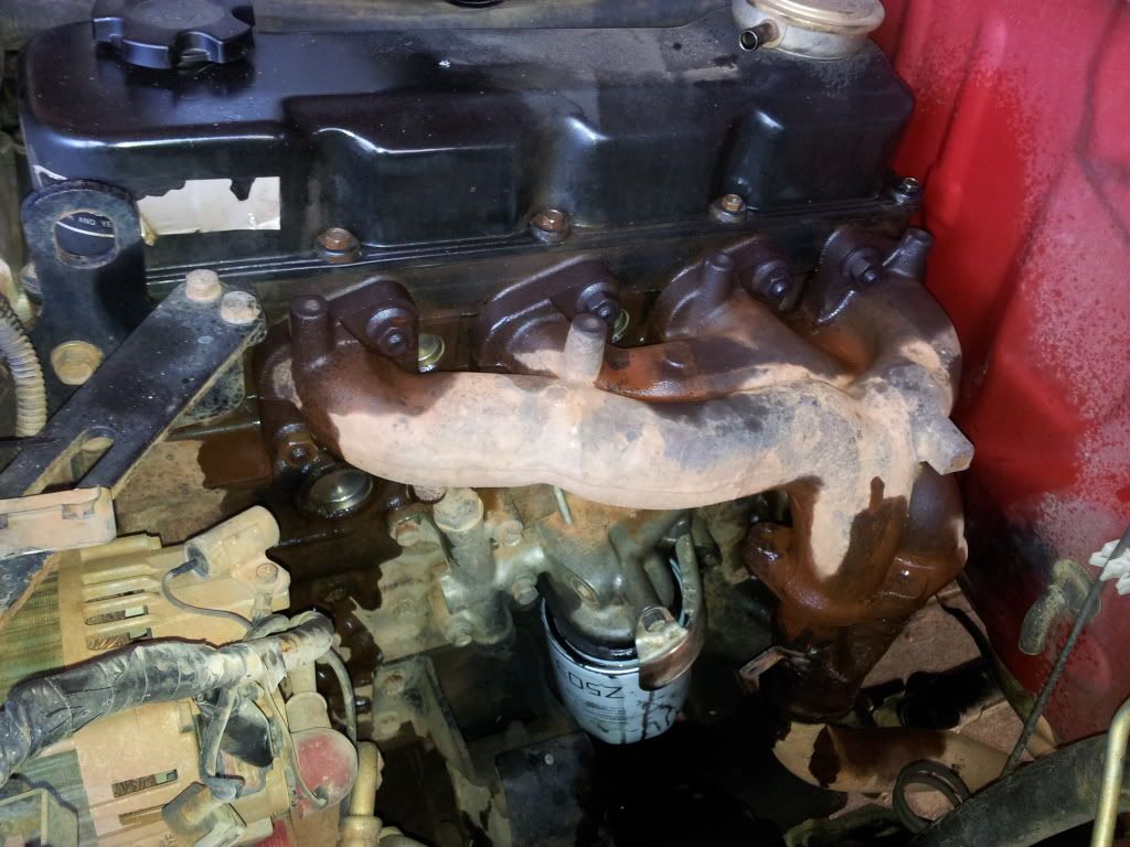
Beginning

IMG_20121228_131049_zpsdcc607f2.jpg


Manifold Off

IMG_20121228_172752_zps80e7d9a9.jpg


EGR Blanking Plate and EGT Sensor

IMG_20121228_173310_zps4f6654d0.jpg


IMG_20121228_155159_zps77974dcf.jpg
 
The turbo and manifold were then bolted on, the nuts on the turb were bloody difficult to tighten up particular the lower left one however got there in the end, you should have fun with that :)

The turbo came with an oil return line and feed line, its a good idea that you pull these off of the car you are getting it from as they pretty bolt straight on. Unfortunately I buggered around with the feed line a bit so not sure if im going to replace that or not but if you dont do anything then it fits straight up QD32 oil filter housing once you remove a aluminium blank.

I couldnt see where the oil return line went and originally thought this would cause issues but upon removing the exhaust manifold it allowed me to see that there was a plug in the hole that aligned with the oil return pipe, good news :)

I had some issues removing the blanking plug on the QD32 oil filter housing for the oil feed line which was seized and when I tried to undo it I rounded it off and thus couldn't use it. Luckily I was also given the TD27T oil filter housing so I threw that on and it fit pretty well. I then went out and bought a replacement filter (Z503) which I assumed would fit only to find that it didnt. Turns out the TD27T uses a different filter to the one used by the TD27s that came in the D22 so dont get that, get the Ryco Z416. Another trip to repco and I had that sorted. Its a slightly larger filter which I initially had concerns about fitting but it seems to be fine and shouldn't be that much more difficult to remove. On a side note I now have a perfectly good Z503 to donate to someone in Adelaide if they need to change their oil :)

The next step was to start figuring out how to connect the turbo with the manifold. There wasnt alot of space and I was pretty unhappy for a bit. The turbo outlet pipe which is on the standard terrano which I had been given is a 1.75'' OD pipe which needs to transition to a 2.5'' OD on the intake manifold. I couldn't find any silicone piping transition pieces which went from 1.75 to 2.5 and two transitions would take up too much space so I didnt know what to do. Anyway I went back with a mate and we had a chat and ultimately decided that we'd put some packing between the outside of the pipe and the inside of a 2'' ID silicone pipe to 2.5'' and then use a 45 degree 2.5'' bend. The two silicone fittings were joined using a piece of PVC. The result is fairly agricultural looking but im fairly happy with it.

The pod filter shown is not connected yet and is just temporary till I have time to source a 80 series airbox and put it in there. Im currently lacking a snorkel so figured id combine the two activities at some point in the future. I had also sourced the original filter to turbo induction piping which connects up to the crankcase vent pipe. If you can you should probably grab this. I plan to put a catch can in there as I hadnt realised how much muck accumulates in your induction lines! Its pretty disgusting really.

Turbo and Manifold

IMG_20121229_143033_zpse0808608.jpg


Oil Return Location

IMG_20121229_115052_zps6c66758f.jpg


TD27 Oil filter Housing, Oil return plug on the right and oil feed banjo on the left

IMG_20121230_120707_zps3dfdb67c.jpg


Intake Manifold Connected To Compressor Outlet

IMG_20121230_175723_zps0b38a845.jpg
 
Next step is to source a gasket for the turbo compressor outlet flange as the one I have is rooted. Ill head into a Nissan dealer tomorrow to see what they want for one but Im guessing its going to be expensive and take weeks to come in from Japan. Not necessarily my ideal solution. You can see the stuffed gasket below

IMG_20121230_205109_zpsf9af1b98.jpg


Ive been tossing up the idea of using a thin bead of high temperature silicone around the edge but given how tight the silicone hosing is in the whole arrangement im worried that when trying to line up the bolt holes ill just smear it everywhere and it will end up in the tube itself.

Anyone got any thoughts on this?

The next step is to procure a replacement oil feed hose( or use my existing one), connect up the water feed and return lines which I already have a plan for and then route the gauges. Not sure where im going to tap the boost sensor into yet.......

Have spoken to an exhaust shop down the road who will do me a 2.5'' system for $830, which seems a little pricey but not really sure. He wasnt willing to replace the dump pipe as he said there wasnt much space which I agree with but the plan was to cut the flange off the piece of exhaust that connect to the dump pipe and go bigger from there. Not much I can do about the dump pipe unless I go to one of the zd30 custom ones for around $300 which im not convinced will do that much, though I could be wrong...

Anyway thats where I am today, 3 days of assing around and it feel like there has been some progress, good thing im on annual leave for another week :)
 
Well went to Nissan and they happened to have a gasket to suite the turbo flange so aren't I lucky, apparently the only one in stock in aus too! Could be the start of a good day! :)
 
Nice job, one thing I'd do straight away is get rid of that PVC and go to an exhaust shop ans get them to expand one end of a bit of 1.75" pipe to 2.5" and use that, the temp that comes out of the turbo won't take long to melt that and you don't want it going into your motor. I think you'll also find as soon as you try and drive it on boost it will just blow hoses off.

I've been down that road before, lol with an mq sd33 patrol that I turboed, I got a shop to make me a 2"-2.5" bit of pipe and I had a hose blow off that on the freeway until I put a bit of a lip in the end of the pipe.

Apart from that nice job and good luck with it
 
according to the interwebs PVC starts to melt at 150 deg C and I did some quick calculations to see what the temperature of compressed air at 10psi (from atmosphere) is and its only around 80 degrees, even given a bit of head room for heat absorbed from the compressor housing I wouldn't have thought it would get that high.

I may be wrong here, you've obviously had a failure! I don't even need an expansion all I need is a straight piece of 2.5'' steel as the silicone 2.00 to 2.5 does the job with a bit of the old hose packed in there. Its tight as! :)

Given im getting the exhaust shop to do some work next week ill probably get them to throw in some scrap 2.5'' to use in there.
 
can't say i've had a failure, but even though the temp is within the range it should handle i wouldn't want to run the risk. the temperature may seem ok, but that's not including what the ambient temp is. even if it only starts to melt at that temp, it will get soft a fair bit lower than that, which is when you will run into problems.

i was more just getting at how tight the clamping needs to be without a lip on any pipes to stop them blowing off under pressure. running at 10psi i really don't think that doubled up pipe on the turbo outlet will hold on for long. my patrol stock was running at about 6psi and that was blowing a hose off until i made a small lip in the end of the pipe. a while after that i intercooled it and upped it to 10psi but didn't have any more issues with pipes coming off.

in saying all that it may be ok, until you get it up and running it's hard to say.

nice write up though and a good lot of pics there, should help someone else out if they want to do the same thing
 
Alright another update :)

Plumbed the water lines in, I used the heater feed and return lines just like bvandermaat and it seems to work fine, there is definitely hot water in there though im not sure that im getting the convective cooling effect once the motor is off that I would like, oh well! I sourced the standard turbo coolant lines and had a 5/8 barb brazed on to match the coolant lines. Then just used two 5/8 tees to supply the water.

Had a tonne of issues with the oil feed line as there was a hairline crack in the aluminium reducing bush that went into the oil housing and took the M10 banjo bolt. This resulted in a nice steady leak, a trip to Nissan and looking at their drawing didn't fill me with confidence as the part wasnt even on their drawings and speedshops didnt seem to be able to reduce down from an 1/2'' NPT thread to a metric M10x1.25.

My solution was a trip to Pirtek where I picked up a a/2'' NPT brass bung and drilled out and tapped the thread myself, problem solved! Seems to be doing alright so far and appears to be holding pressure.

Water Feed(Right) and Supply(Left)

IMG_20130101_145740_zps02bfb5a0.jpg


Water Feed

IMG_20130101_145758_zps98789cad.jpg


Water Supply

IMG_20130101_145749_zps7fe3c706.jpg


DIY Reducing Bush

IMG_20130103_135126_zpsee8c4782.jpg
 
Ive also been to the exhaust shop and had a straight through system fitted, its probably a bit loud (ie illegal) but its pretty good in the cabin when driving and cruising revs. I ended up ditching the stock dump pipe and using a after market ZD30 dump pipe as the flange is exactly the same, the amount it opens up the throat of the pipe is amazing and well worth it in my opinion. Though it may have made it quieter hehe. The exhaust guy mentioned that the dump ipe clashed with the front diff a bit so he had to modify it so that there was clearance but other than that it fit pretty well!

Ive also got a piece of scrap 2.5'' pipe as suggested to replace my temporary PVC fitting in the intake section. Im glad I did, I pulled it out and it had already started to warp due to the heat! I am in the process of attaching a fitting to it to plumb my boost sensor onto and then I can start with wiring that baby up. Still not sure how to get the wires back into the cabin though. Any suggestions?

Dump Pipe

IMG_20130103_135234_zpsbc003145.jpg


Dump Pipe and Turbo

IMG_20130103_135259_zps82ee6f68.jpg
 
Great work mate, it looks excellent. How are you liking the power difference.
I still love it. The next best mod to do would be a bigger airbox as you can notice a smoother increase in revs.
 
Finally there was this fitting here which appears to be associated with the water cooling lines. Any idea where I might be able to fit that?

IMG_20121201_134750_zps2a751ae4.jpg

Might not matter now, but on my TD27, that attaches into the block below the turbo. From another of your pictures, you've got a plug in that position I can see, a bronzey coloured thing with a deep hex head.

On holidays at the moment, so I can't go and check and see what it's connected to.
 
I havent played with the fuel pump yet but it definitely seems more torquey and a bit more responsive. Im assuming this is because the extra air is allowing the fuel to combust better but it could be just a result of the bigger exhaust? Anyway once I get my boost and temp gauges fitted up ill start looking at ramping up the fuel a bit.

How did you run your sensor wires into the cabin? I cant seem to find an appropriate spot.

As for the water return/feed plugs I actually got some drawings from Nissan while trying to track down the reducing bush and figured they must have screwed into the block somewhere but had no idea where. Ive played iwth it all way too much now for it to be of any use now unfortunately :( Meh it appears to work fine though the way it is.
 
Small update, went for a burn a weekend or so ago in the sand and had a great time. Found that I really need to do something about my air intake. On hot days its quite noticeable the drop in power due to sucking in hot engine bay air. Time to start looking for a airbox solution I think.

IMG_20130124_190110_zps483aeb32.jpg


IMG_20130124_190806_zpscc85cb58.jpg


Went down on the beach and shat myself when I got stuck. Lucky I had some mates there, maxxtraxx got me out really easily. Was surprised actually.
 
Last edited:
Have finally gotten around to the to do list and knocked a few more things on the head. I fitted an 80 series land cruiser box. Its made a noticeable difference as bvandermaat suggested it would, much smoother across the rev range. I added a snorkel at the same time, not sure if this will have helped much though. Its an ebay jobbie and the install went relatively well, though now I don't have an indicator :S Ive added in the crankcase air recirculation line though I need to add a catch can at some point. Not sure how well the epoxy I used will go(Araldite) it doesn't seem to get too hot there, it is on the induction side after all, and is supposedly rated up to 100 deg.

Airbox Fitted and Plumbed

IMG_20130421_093151_zps5cb093e6.jpg


Crankcase recirculation line plumbed up

IMG_20130426_174902_zpsa78d9e70.jpg


Snorkel!!!!

IMG_20130408_091042_zpsd5c287b5.jpg
 
Also had a play with the fuel pump today. For those that don't know ive pointed out where it is under the intake manifold. I did a bit of research as to the best way to approach this and found a really good resource for the Bosch VE fuel pump. This can be found here

Essentially I wound the Full load adjustment screw in a bit which essentially delays the spill point for the fuel delivery piston in the pump and makes the injection period longer across the range. To counter the higher idle speed I was now getting I wound the idle adjustment screw back a bit. The D22 manual specifies 750 RPM +/-50 but that seemed a bit high to me given it was previously only around 500, though it did get a bit shaky at times lol. Anyway the only issue I can see with this is that my engine RPM limit is now a bit higher but from what I understand if I adjust the high rev limit adjustmnet screw ill lose the extra piston distance ive now got so Ill just have to make sure I dont blow my engine up hehe.

Current plan is to watch it for a bit and see what my EGTs get to under extended duration driving such as a trip on the highway, Based upon those results ill either wind it up a bit more or lower it. Ill also get someone to follow me to make sure im not putting out too much black smoke! Based upon my lead foot driving test it appears to have a lot more power now. Previously the new exhaust and airbox made the low end alot more responsive but as soon as the turbo spooled up it didnt seem to go anywhere, now with the extra fuel its noticeably better. Just hope my fuel economy doesnt take too much of a hit.

EDIT: One more thing to note is the pump is a bitch to get to, I spent so much time trying to figure out how to get to it, eventually I used a deep 13mm socket on a 150mm extension with a universal joint on it to crack the lock nut and then you can easily adjust the screw, the amount of time I spent trying to turn the screw and not getting anywhere because of the lock nut is almost embarrassing :S

Thar she hides

1103fead-c729-4cbb-8acf-f7a34bccfdec_zpsb4a172d7.jpg


Fuel Pump and Adjustment Points

2e83acfd-4602-4a4b-ae27-b08f7c234011_zpsd439f3ce.jpg
 
Last edited:
keeping an eye on this, loving the build.

ill be doing some similar things when my d22 is road reg'd
i already have the complete turbo setup from a terrano.

with your air intake, using those silicon bends they will suck in, unless like the factory ones they have the metal springs coiled up inside of them...have you thought to replace this with a solid metal pipe?

is your snorkel on of the ebay specials?
would you mind showing me a picture of the snorkel connection in cabin?
do you know the connection size of it? is it 2.5inch, 3uinch, or?

cheers, christian!
 
The silicon bends don't seem to suck in. The major joint where I joined a 45 deg bend and a 90 degree one has a fair bit of 2.5 inch exhaust pipe as a joint which seems to make it stiff enough.
I'm not sure I can show the snorkel to airbox connection in cabin as I've siliconed it all up and it was a pain to get in there. I'll have a look when I get home and see if I can take any useful photos. My guess is that the inlet and outlet for the 80 series airbox is 2.75" as it was tough fitting the 2.5 over it.
Yeah I picked it up from eBay for around 130. Seemed like a steal. Only issue is I've had to remove the indicator on that side
 
Hey mate, sorry to hi-jack your post, very interesting and am thinking of doing this later to my qd32, just wondering thou.

Your above photo of the injector pump, I've been looking in that manual for the air bleed screw and what I am seeing in the manual is not what i'm seeing on the pump, that screw below the banjo bolt on the pump in your second pic, is that the air bleed screw??

If not would anyone be able to tell me where it is or have a photo of it, I've looked online and couldn't really find anything on it, so you seem that your know you way around the pump.
 
With my sd3.3 and td27 i have always bled the pump by using the primer on the fuel filter
then while running the engine - slightly cracking each injector collar. you will need to do it slightly and some diesel will escape but so will the air. then re-tighten, it do-sent need to be open long.
not sure if its the approved method, but ive never had an issue after doing this.
 
Will any 80 series air box be suitable for the QD32? or does it have to be from the diesel?
I havent done turbo conversion yet but want to in the future. Although at current because I have done a body lift the mounts on the factory air box have torn apart and snapped, so wanted to replace it, may as well get something better.

Also are any of you guys running 33" tyres on a QD32? Im looking at getting some soon but concerned that without a turbo im going to loose a heap of power.
 

Latest posts

Back
Top