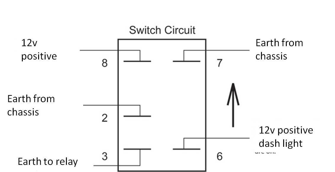
I'm going to assume that the switch is a double pole single throw, and the upper links in the diagram are NOT switched by the switch. If they are switched, then when you flick the lever down, the chassis earth will connect with the 12V feed and blow the fuse (or start a fire if you forgot the fuse).
The original wiring actually sounds right. Your relay has (usually) 4 poles on it. Two of these are for triggering the relay and are usually numbered 85 and 86. The other two are for the fused power source (usually numbered 30) and the output (usually numbered 87). If you have a relay with 5 pins, it will have a pin numbered 87a as well, and this is OFF when your the relay is active and ON when it's not. Don't use pin 87a normally - but the relay itself is fine to use in this situation.
Knowing how a relay works helps too. Positive to either 85 or 86 - and negative to the other. Let's say positive to 86 and negative to 85. Doesn't matter which way around it goes, it's just a coil that operates the relay (which really is just a switch). Can go either way, who cares. If you connect 86 to the headlight high beam wire (which obviously only comes on when high beam is on) and the other to negative, the relay will come on whenever high beam is on. With pin 30 to a fused positive source, and pin 87 going to your driving lights, your driving lights will come on whenever your high beam is on.
Now, to make it a little nicer, don't earth pin 85 straight away. Bring one wire in from pin 85 to the cabin on to one side of the switch. Connect a short lead from the middle of the switch to earth. Now, when high beam is on, the driving lights will only come on when that switch is on. If the high beam is on and you turn the switch off, your high beam stays on but the driving lights switch off. The switch turns the driving lights on and off but they'll ONLY work when high beam is active. And the law likes it working like that too.
I hope that's clearer. If your switch has lights inside it, you might need to work a little magic, especially if those lights are LED-based, because LEDs need a particular orientation (positive on one leg, negative on the other) in order to work.


")