RLI
Member
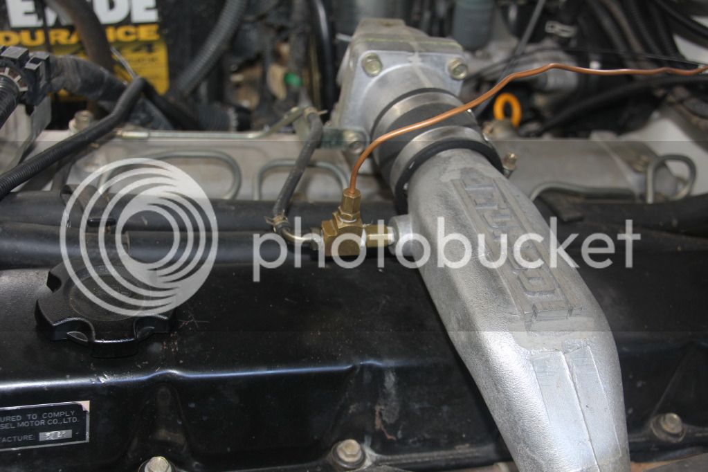
I purchased a brass block fitting from my local Pirtek store. (when purchasing the block, take both the Nissan and after market oil pressure sender units to the store, so they can match the threads accordingly) Now that i have my brass fitting, firstly, i fit the Nissan oil pressure sender unit to the top of the brass block (don't forget to use thread tape)
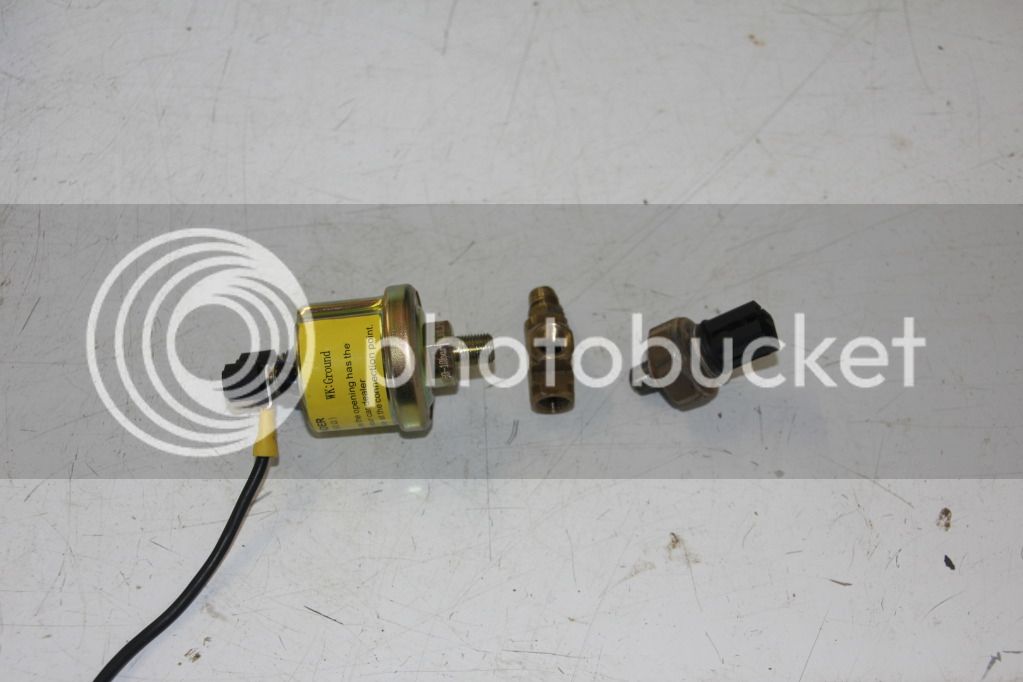
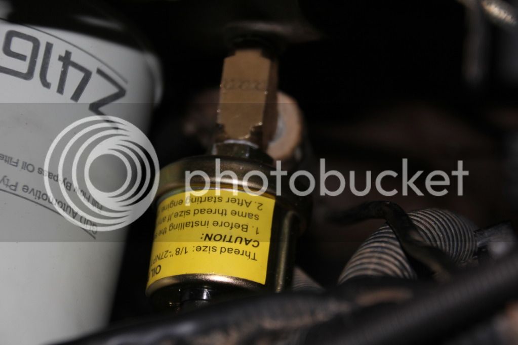
Secondly, Now fit the brass block fitting with the Nissan oil pressure sender unit to the engine block using a 6inch shifter (don't oven tighten) Then fit the aftermarket sender unit at the end of the brass block fitting facing towards the drivers side guard.
Remove factory plug from thermostat housing and Fit water temp sensor fitting here. Remember to use thread tape! If your fitting will not fit, go to your local Pirtec store with thermostat housing and your sensor, so you can fit a reducer two way fitting.
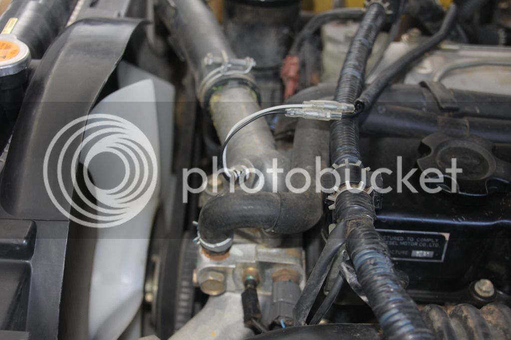
more to follow over!
Secondly, Now fit the brass block fitting with the Nissan oil pressure sender unit to the engine block using a 6inch shifter (don't oven tighten) Then fit the aftermarket sender unit at the end of the brass block fitting facing towards the drivers side guard.
Remove factory plug from thermostat housing and Fit water temp sensor fitting here. Remember to use thread tape! If your fitting will not fit, go to your local Pirtec store with thermostat housing and your sensor, so you can fit a reducer two way fitting.
more to follow over!