RLIs Nissan Patrol rebuild under way

Nissan Navara Forum

Help Support Nissan Navara Forum:

This site may earn a commission from merchant affiliate links, including eBay, Amazon, and others.
RLI good build.

How much was your armadas? what was the valving?

G'evening Cooper,

I paid $250.00 each from Superior Engineering 12 months ago!

I went with the Amada Xtreme 2" GU lift Front and Rear Shock's. Valving medium to firm to suit my towing needs and carrying over 500kg in weight when fulled loaded, ready to tour!

Superior Engineering currently are selling them at $265.00 each including free delivery!

I have had mine now for twelve months and they are fantastic, especially on corrugated roads!

I also fitted 2inch King spring coils!

Regards,

RLI
:shotgun:
 
TD05 Turbo install.

TD05 16G Turbo install!

G'day Trendsetters,

The following is my interpretation of a TD05 16G (Ye-Haa) turbo install! Matt Craig from United Fuel Injections, please correct me if i am wrong please!

PART I (remove old turbo!)

Disconnect the negative battery terminals. Remove radiator cap and undo bottom radiator hose draining coolant into a container. Undo the 4 clips on top of the air-cleaner and undo the large clamp that attaches to large black plastic air duct intake pipe to the turbo. Remove the air cleaner lid. Undo clamp on turbo and disconnect black pvc hose from air duct pipe, then remove air duct intake pipe from turbo.

Disconnect the 2 x clamps that hold the small aluminium pipe to the inlet manifold and the clamp that holds it to the inlet side of the turbo and also remove the thin black rubber vacuum tube and then remove the aluminium pipe from vehicle.

IMG_1517.jpg


Spray WD40 or CRC on the 6 x 12mm nuts on the heat shield, the 4 x 14mm bolts on that attach the turbo to the exhaust manifold and also spray the 3 x 14mm dump pipe nuts.

IMG_1511.jpg


Undo the 3 x 10mm nuts on turbo inlet housing and remove the aluminium elbow housing. Now undo the 6 x 12mm bolts that hold the heat shield to the manifold and remove from vehicle. Using a 14mm spanner and a long piece of pipe/tubing. Gentle, crack open the 4 x 14mm turbo/exhaust manifold nuts. Do not remove nuts at this stage.

IMG_1512.jpg


more to follow over!
 
Now gentle crack open and undo the 3 x 14mm dump pipe nuts and the 2 x 13mm nuts that hold the exhaust to the middle muffler section of your exhaust. Using a 22mm spanner/socket disconnect and remove the 2 x water lines from the motor to the turbo.

IMG_1514.jpg


Using a 12mm spanner undo and remove the 4 x 12mm bolts that attach the oil feed line and return lines to the turbo. (Place rag on floor first to catch small amount of oil) Now remove the 2 x metal tube oil lines.

IMG_1519.jpg


sing a 14mm socket with long breaker bar, gentle crack open and undo the 3 x 14mm nuts and remove the turbo support mount. Gently push down the exhaust pipe from the dump pipe, now remove the 4 x 14mm turbo/exhaust manifold nuts. Gently push down and twist the turbo up to free it from the vehicle. Walla, one removed turbo!

IMG_1525.jpg


more to follow over!
 
PART 2 (comparisons)

Note size of new TD05 16G inlet housing with purple actuator compared to factory HT18 turbo

IMG_1547.jpg


Note the size of the new 3inch dump pipe v the old factory dump pipe also note the restriction in the bend on the factory dump pipe compared to the 3inch. It is so important to get diesel engines to breath properly.

IMG_1548.jpg


Note: the size difference on the factory outlet compared to the new replacement outlet from United Fuel Injections. Also note the restriction in the factory set-up. Matt Craig's new stainless steel outlet will now let this baby get the air that it needs.

IMG_1505.jpg


more to follow over!
 
PART 3 (preparation)

To make things easy, i welded the 3 x 14mm bolts to the dump pipe, this makes it a lot easy to install.

IMG_1503.jpg


I also fitted the 90 degrees silicon pipe and the stainless braided oil line to the turbo. Boil hot water to help flex the silicon pipe onto turbo inlet housing (it makes life a lot easier)

IMG_1549.jpg


I modified a 14mm openender spanner to tighten up the rear exhaust dump pipe nut (the one closest to the firewall) Length of spanner when cut should be 100mm. Use a cheap supercheap spanner ($2.00)

IMG_1562.jpg


more to follow over!
 
I also modified a 9/16 AF openender spanner to tighten up the oil braided feed line to the turbo. Same again, use a cheap supercheap spanner ($2.00) I just grinded the sides so it could fit and tighten up the nut.

IMG_1570.jpg


Clean all the oil and crap out the air duct pipe.

http://i1067.photobucket.com/albums/u434/RLI1/Turbo%20photos/IMG_1565.jpg[/IM

Fit the 2 x allen key water bung plugs radiator hose housing and to the engine block.

[IMG]http://i1067.photobucket.com/albums/u434/RLI1/Turbo%20photos/IMG_1556.jpg

more to follow over!
 
Using a 9/16 AF ring spanner. Fit the new oil line adapter to the engine block.

IMG_1551.jpg


With a grinder cut the black plastic outlet from air cleaner lid.

IMG_1540.jpg


Use a 90mm (NOT 100MM) hole saw to cut out center. I screwed the lid to bench then cut out the section that need to be cut out.

IMG_1541.jpg


more to follow over!
 
File back all jagged and rough edges.

IMG_1544.jpg


Make sure you measure the angle of the new stainless lid to the black factory air duct tubing going to the turbo. Temporary place turbo with air duct attached to manifold. Now measure correct alignment for angle required to air cleaner lid outlet (stainless). Measure twice drill holes once! Drill the 2 holes for the stainless lid, use Sikaflex 227 sealant to help give that waterproofing. Use the two allen key counter sunk bolts supplied to secure stainless lid to factory air cleaner lid.

IMG_1577.jpg


Check that new hole in air cleaner lid is same diameter as new stainless lid.

IMG_1505.jpg


Part 4 coming tomorrow!

Regards,

RLI
 
PART 4 turbo installation.

Using exhaust gasket sealer coat both sides of the turbo manifold gasket and fit to exhaust manifold. If you have an EGT gauge, remove the plug in the dump pipe. Now fit the turbo to the exhaust manifold and the 4 x 14mm nuts. (do not tighten up the 4 x nuts for now) Now fit the exhaust dump to the dump pipe on the turbo using the 3 x 14mm new nuts and washers supplied with your turbo. Now re-bolt your exhaust dump pipe section back to the middle muffler section of your exhaust.

IMG_1560.jpg


Now tighten up the 4 x 14mm turbo manifold nuts. Remember to use your cut down 14mm spanner for the rear firewall nut. Then tighten up the 3 x 14mm dump pipe nuts and the 2 x 13mm exhaust flange nuts. Note when installing the far rear dump pipe exhaust washer and nut to the bolt. Because of the tight and awkward position of that dump pipe bolt. Coat one side of the washer with exhaust gasket sealant and stick it up onto the bolt flange face, then attach the nut.

IMG_1563.jpg


IMG_1564.jpg


Now attach the oil feed line to the block using a 9/16 AF spanner. Now fit EGT probe to dump pipe. Using a 12mm spanner/socket, re-fit the heat-shield and the 6 x 12mm bolts. Note, old factory dump pipe heat shield will not fit, discard.

more to follow over!
 
IMG_1571.jpg


Now fit the silicon elbow and 2 x clamps to inlet side of turbo and re-fit the small aluminium inlet pipe and 1 x clamp to inlet manifold outlet. Connect the thin black rubber tube to from injector pump to the fitting on the side of the small aluminium inlet pipe. Remove the black rubber end from the black air-duct section that fits to the new 3inch 90 degree silicon elbow from turbo housing. This should just slid off using WD40 or CRC. The new 3inch 90 degree silicon elbow will not fit the black air-duct section, until you cut out the inner section. The outer section of the rubber clamp will allow for the new 90 degree elbow to fit. Don't forget to fit the 3 x clamps clamps to the black air-duct and the blue 90 degree elbow before fitting these two together. Also fit your PVC tube from the rocker cover back to air-duct section.

IMG_1578.jpg


Now fit air cleaner lid to air-duct section and clip back to air cleaner box. Double check that all bolt's, clamp's and nuts are tightened up properly. Re-fill the radiator will coolant and re-connect your battery or batteries. Walla your done! Time to start your beastie!

One other thing we do before start up was prime the turbo with oil. In this instance we disconnected the fuel cut off solenoid from the injector pump, this effectively stops fuel being injected and the motor will just wind over, and cranked it over a couple of times allowing oil to get to the turbo. You can also pour a small amount of oil into the top oil line prior to initial start up.

PS, Tune-up section tomorrow.

Regards,

RLI
 
Last edited:
Part 5 tuning!

G'day day lounge lizards!

After fitting the turbo nissannewby and i took the Patrol for a test run. We were not overly impressed at first, she struggled to pull 11psi. That afternoon i took nissannewby's girlfriend for a quick spin up the Morbid trail on Mt Coramba about 10 clicks west of Coffs Harbour. Everything was going fine about 3/4 the way up the track when all of a sudden black smoke clouded the back of the Patrol, at first i am thinking, fark a severe thunder storm was rolling in. I just made it to the crest of this hill when the poor old beastie shit the whiskers! I pulled over to one side of the track and opened the bonnet, by this time nissannewby pulled up and we started to investigate what the problem was.

nissannewby, got me to rev the engine a couple of times, then he suddenly found the cause of my problem. Both the new silicon hose's were collapsing in on themselves after revving the engine.

IMG_1609.jpg


We headed back home and contacted Matt Craig from United Fuel Injections in Western Australia for advice. Matt Craig advised us to start looking for an obstruction in the snorkel air-cleaner area. nissannewby was quickly into the problem solving mode! I really admired young newby's ability and professionalism when tackling problems. Firstly, he removed the air-cleaner lid, revved the engine, this time the hoses did not collapse. Turbo end fine!

Secondly, we removed the snorkel head and nissannewby shone a torch inside the snorkel to see if he could see anything causing a blockage. Nothing! We decided to pull the guard off with the snorkel attached (which is a lot easier that ripping your farken hands apart trying to undo the snorkel internally.

more to follow over!

:rambo:
 
Last edited:
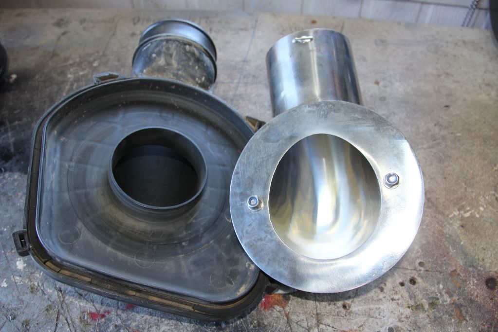
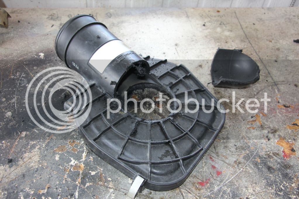
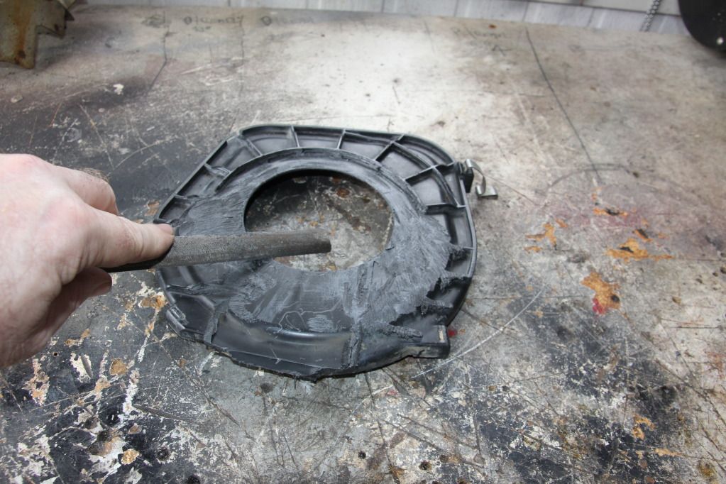
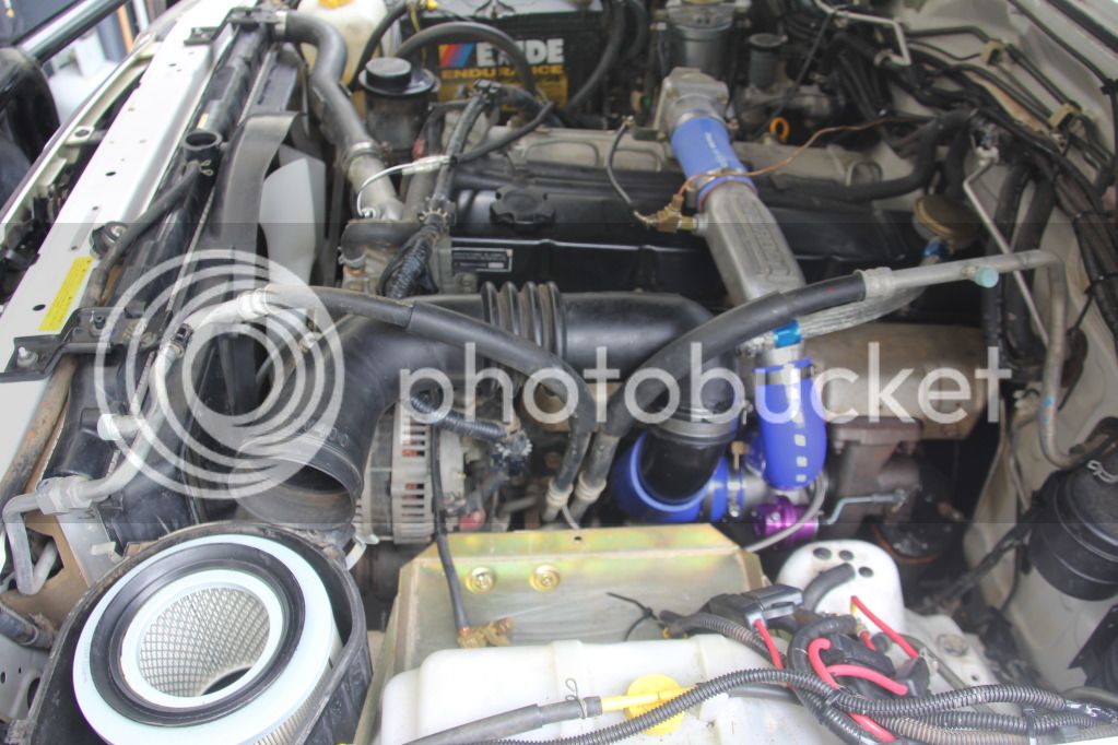
With the guard removed and snorkel removed we revved the engine again and the hoses collapsed. Now we removed the inner snorkel tube and revved the engine again. Still the hoses collapsed. Mat noticed the air cleaner canister looked odd were it fitted into the side of the guard, connecting into the snorkel housing. Walla, he discovered the problem. Someone had fitted a flexible tubing inside the snorkel housing which then connected into the air cleaner canister. What was happening under load (revving) she was breathing, however, as soon as you stopped the revs, the vacuum sucked the flexible tubing into the air-filter causing an obstruction resulting in the hoses collapsing, which then causes only fuel to the motor and no air, resulting in a stalling effect.

IMG_1610.jpg


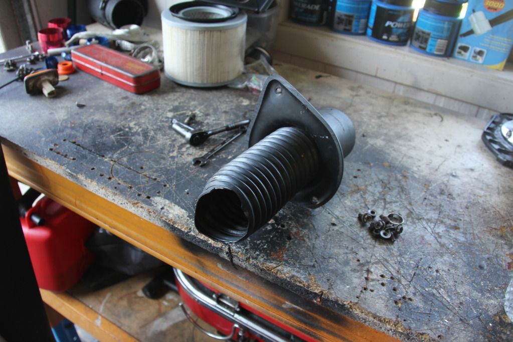
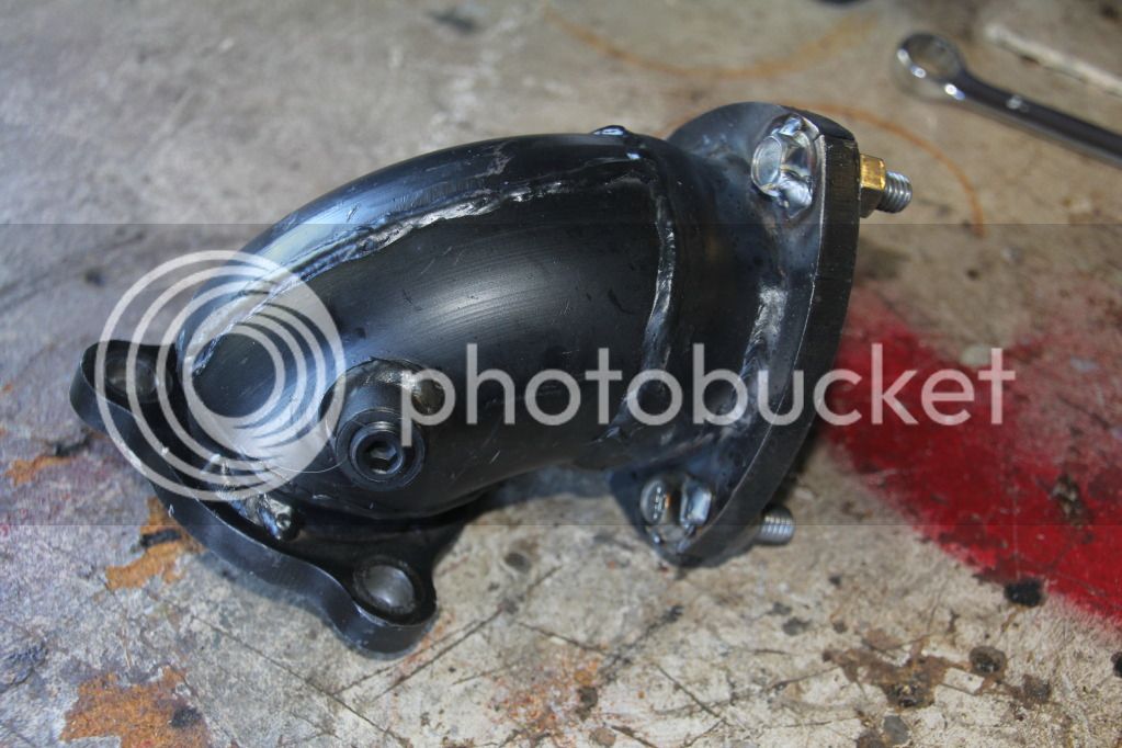
On closer investigation, i noticed faded writing on the passenger side guard. What i surmised was that the Patrol had been in an accident and suffered damaged to the passenger side guard, the repairer replaced the snorkel and guard, however, they did not replace the air cleaner canister which was damaged. They simple cut off the damaged outlet section that fitted into the guard and simple fitted 60mm flexible tubing from the snorkel inlet housing into the air filter canister and used a shit load of silastic to seal the joint. ( A couple of days latter, I rang the previous owner whom confirmed that the Patrol had been hit on the passenger side and had the snorkel and guard had been replaced by a local panel beater in Keillor, Victoria)

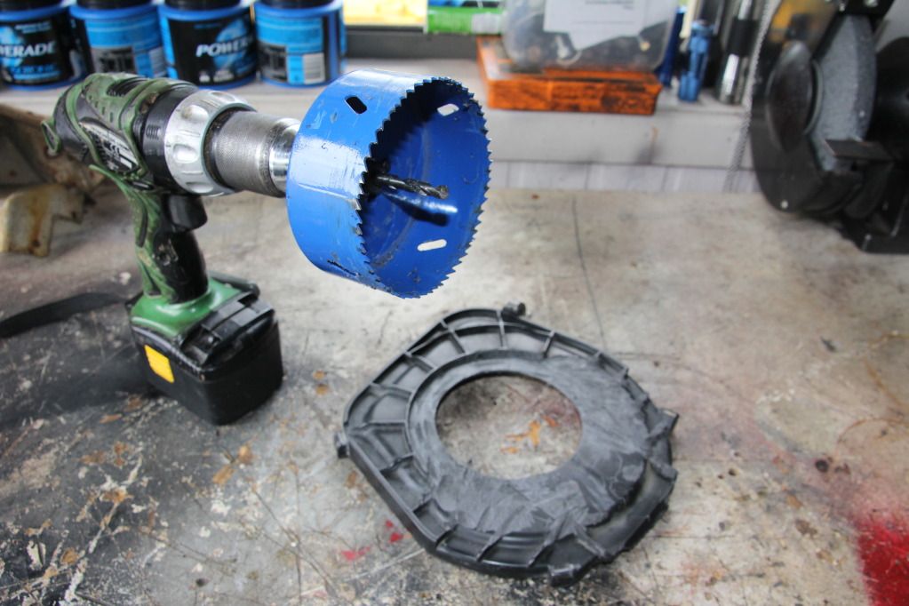
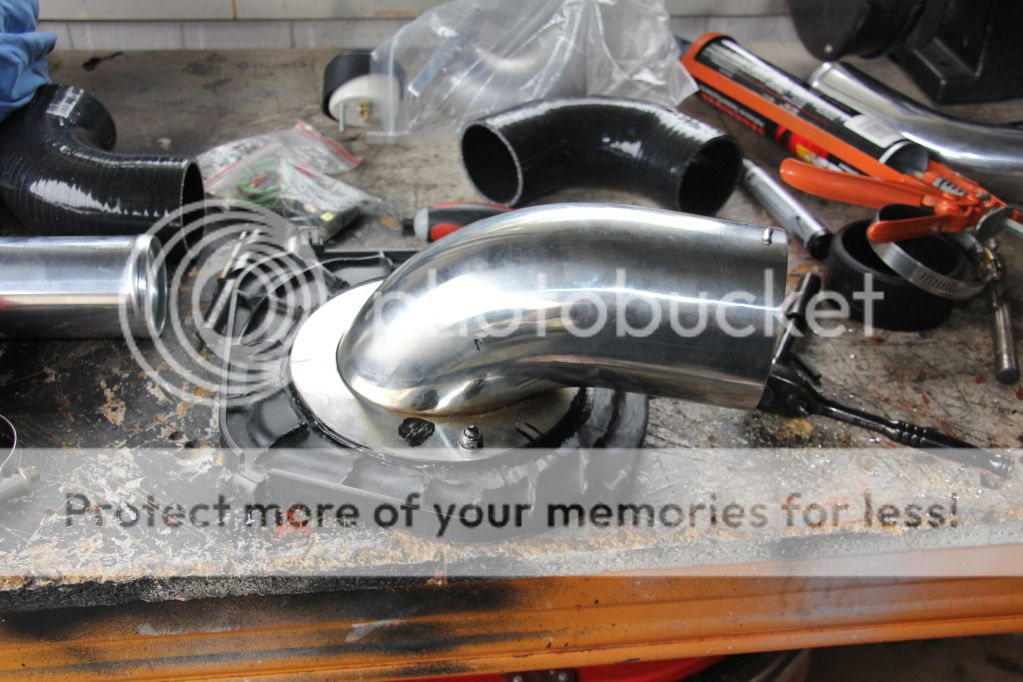
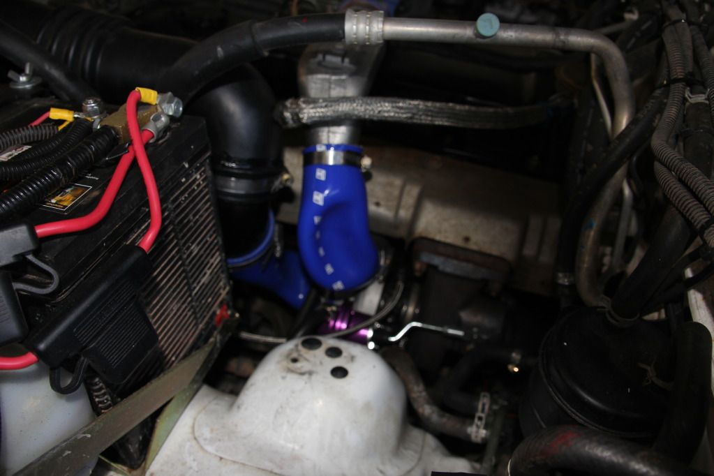
nissannewby and I went to the local hardware store picked up a 90mm plumbing fitting and some 90mm pipe, viola, problem fixed !

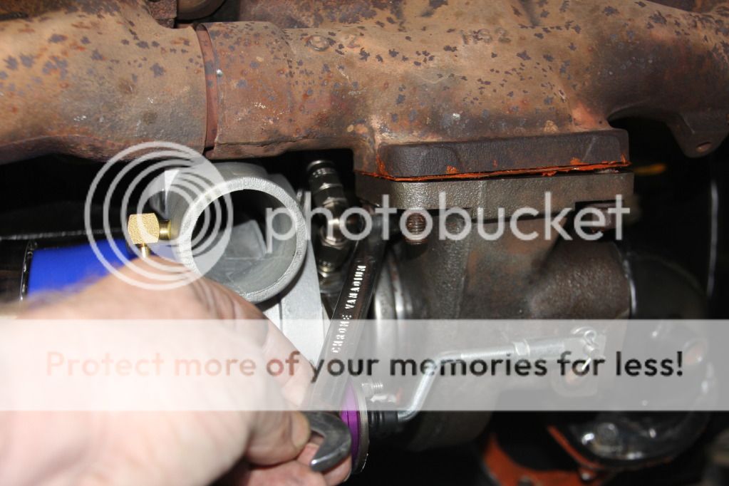
nissannewby contacted Matt Craig from United Fuel Injections, advised him of the situation, he laughed, has he advised us that he has seen some horrid modifications that have come into his workshop over the years. Matt Craig then guided young nissannewby on how to adjust the injector pump.

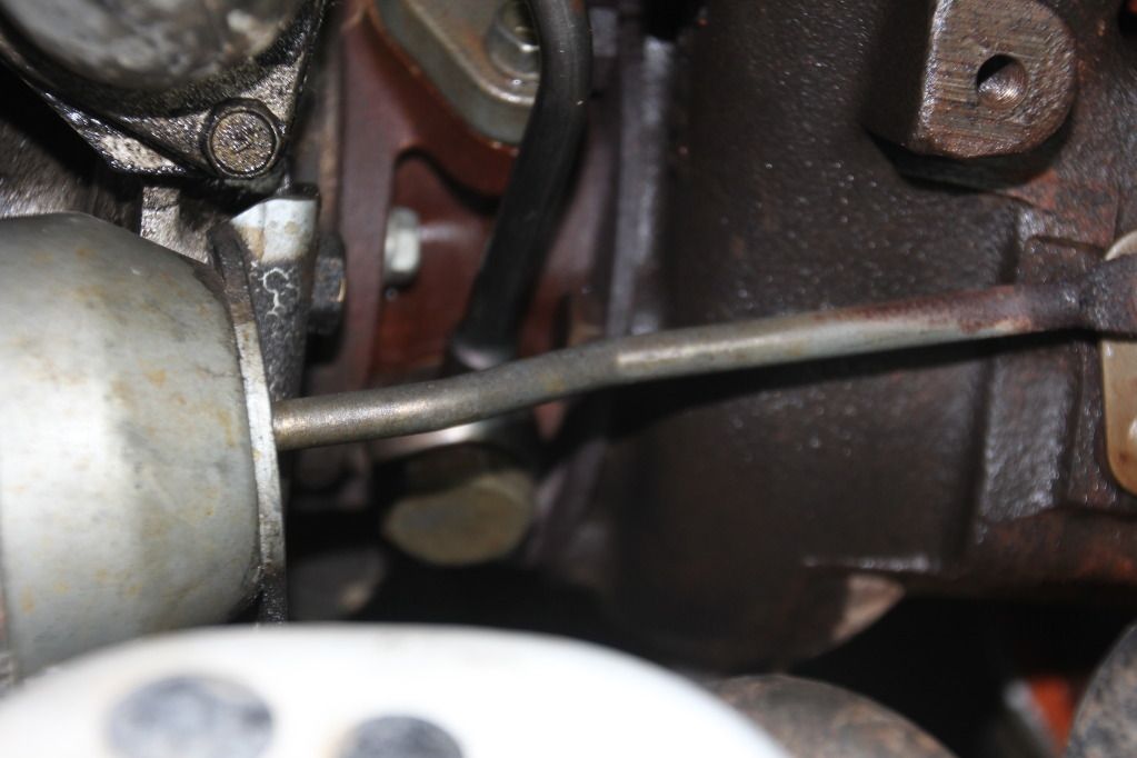
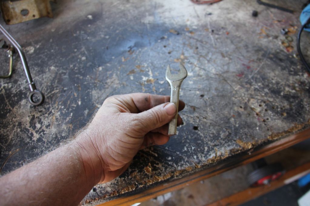
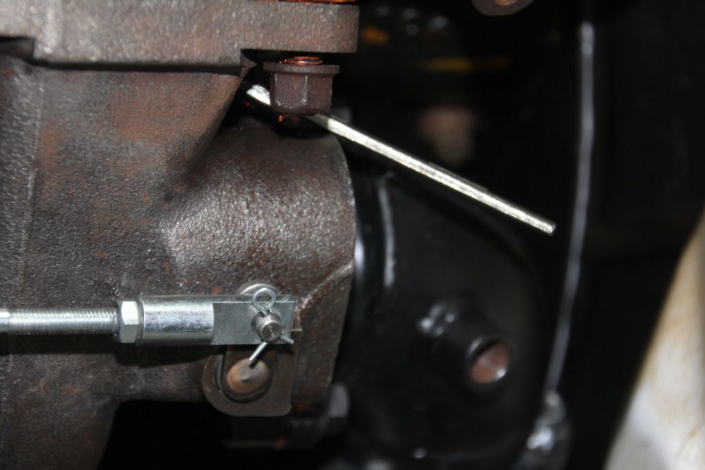
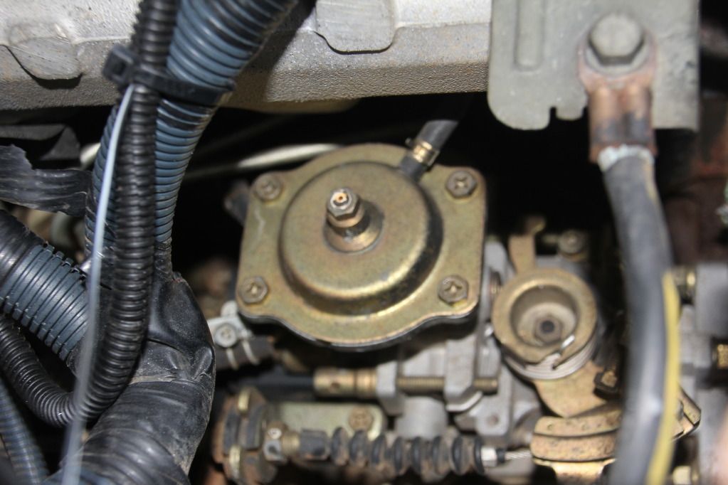
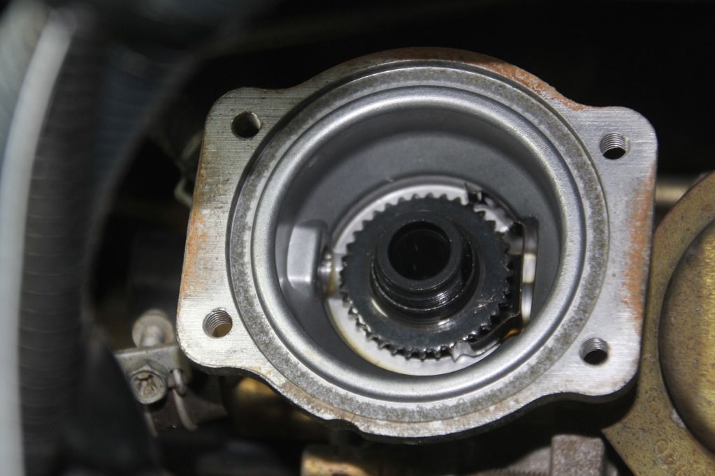
Firstly, undo the 4 x 10mm bolts that hold the diaphragm cover. Gentle remove the cover, mark the diaphragm location with a sharp scribe/nail. Remove the compensator diaphragm and place on a clean rag and cover it.

IMG_1653.jpg


more to follow over!
 
Last edited:
Now turn the star-wheel clockwise 2 full revolutions. (1 x revolution = 360 degrees.) Do this by pressing down on star-wheel and at the same time, using a flat bladed screw driver, gently twist the metal locking tab from the teeth to allow you to turn the wheel. Turn the boost compensator 90 degree's and re-fit back into pump. (Look at the offset on the bottom of the pin and find the deepest part of the offset concentric and turn this towards the front of the engine.) You are now delivering more fuel at full load.

IMG_1629.jpg


Now start vehicle and conduct a series of revs under load, whilst checking for any serious signs of black smoke. Now take the vehicle for test run checking both boost and EGT readings. At this stage i was running 14psi at 100ks under-load and my EGT's were 450. Cruising at 100ks at 5psi boost my EGTS were 225 also my water temp was 170 and oil pressure at 60psi.

This is not the end of my tuning, i am yet to fit my Cross Country intercooler and my modified United Fuel Injections inlet manifold. I will keep you posted when i do.

PS, if you are not mechanically minded and do not have an EGT gauge fitted. please do not attempt to play with your injector pump. See a professional diesel tuner to do this correctly for you. If you incorrectly adjust your pump you could do serious damage to your engine! I had the help from Mat (nissannewby) who is a qualified diesel mechanic and Matt Craig qualified diesel mechanic and Director - Vehicle Performance Division from United Fuel Injections to help me tune my Patrol.

PS, 7 MONTHS AND COUNTING TO CAPE YORK AUGUST 2013, YE-HAA BABY, BRING IT ON!

Regards,

RLI
 
Great write up, RLI. Without being a smart-arse, walla is actually spelt voila - it's French and basically means there it is. No need for thanks, just send beer!! Cheers.:cheers!:
 
Great write up, RLI. Without being a smart-arse, walla is actually spelt voila - it's French and basically means there it is. No need for thanks, just send beer!! Cheers.:cheers!:

G'day bullwinkle,

Thanks mate, I am typically Irish with my spelling! Thanks for the correction, i have learned something yet again! lol

Regards,

RLI
:sniper:
 
Radiator install! to GU 4.2 turbo diesel manual wagon!

Firstly, place your Patrol in an area that you can safely discharge the old coolant or place a container to catch the old coolant. Secondly, disconnect both the top and bottom radiator hoses, disconnect the coolant tank hose from neck of radiator, finally remove the radiator cap and drain the radiator of the old coolant! Thirdly, on the 2001 4.2 turbo diesel manual wagon model, disconnect the two fan harness connectors on the side of the radiator. Fourthly, Un-clip and remove the lower radiator shroud. Fifthly, using a 10mm socket/ring spanner undo the 2 x 10mm nuts that that support the top of the tank. See photo below.

IMG_1552.jpg


Now disconnect the air-conditioner support bracket. Then undo the 3 x 10mm nuts that hold the top radiator shroud, see photo below.

IMG_1554.jpg


Now gently remove the radiator.

Fit top radiator shroud to new radiator.

IMG_1607.jpg


Now fit new radiator to vehicle, reconnect two fan harness connectors on the side of the radiator. Reconnect the top and bottom radiator hoses, reconnect lower shroud, using a 10mm socket/ring spanner re-fit the 2 x 10mm nuts that that support the top of the tank. Now re-fit the air-conditioner support bracket. Reconnect the coolant tank hose from neck of radiator to coolant bottle. Finally fill with new coolant. Start vehicle and run until thermostat opens and allows coolant to flow through motor. (Check water temp gauge) Top up coolant and re-fit radiator cap! voila, your done! (thanks to bullwinkles spelling correction!)

Regards,

RLI
 

Latest posts

Back
Top